CATEGORIES
Treating the Facets
Improve the Facet Quality
If the facets after cleaving are mirror-like, this will be already sufficient to create a basic Fabry-Perot resonator and both necessary conditions for sustaining a laser will be given: A gain region and an optical resonator. Due to the Fresnel effect at the semiconductor-air boundary, the reflection at the facet will already be large enough to sustain stimulated emission (InSb ~40%, GaAs ~30%, InP ~27%, GaN ~18%). Low cost laser diodes with low requirements such as those found in CD players do not experience a treatment of the facets for cost reasons. Most other lasers do receive a facet treatment despite the complexity of the needed processing. In order to access the facets, it is necessary to flip them on their side. The common way to achieve this is to build a stack of the freshly cleaved laser bars.
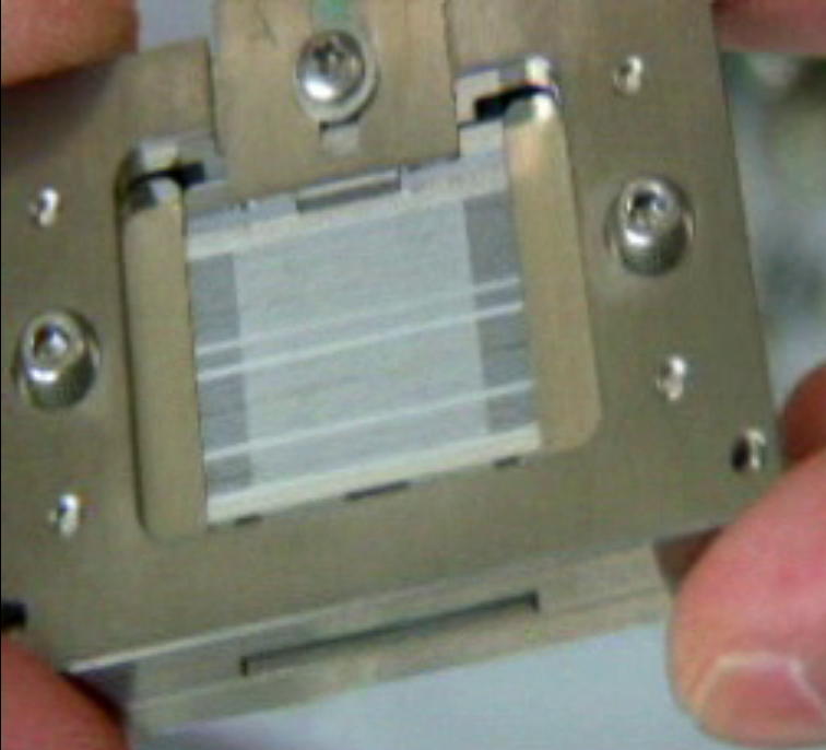
Stacker Jig.
Considerations About Laser Lifetime.
After cleaving the semiconductor a set of vacant bonds appear at the exposed surface caused by the interruption of the periodicity of the crystal lattice. Impurities (especially oxygen) readily attach to them. Their effect is to render the facet partly non-transparent for the laser photons. The absorption at the facet generates a lot of localized heat and causes further facet degradation. Beyond a critical point, that is easily reached with laser power, the positive feedback of heat and absorption leads to an overheating of the facet and an irreversible semiconductor meltdown called COD (Catastrophic Optical Damage) is the result.
By applying two different etalon mirror coatings on both sides, not only the reliability, but also the laser efficiency can be significantly improved. This is achieved by a series of dielectric coatings with alternating diffraction indexes with a thickness that corresponds to the wavelength of the laser. The first mirror ideally reflects all the photons back into the resonator reducing the threshold current and the second mirror allows a precise amount of light to be bounced back into the cavity. The later is the light emitting side of the laser.
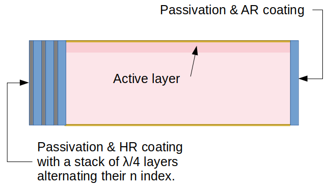
Side view of an edge emitting laser with its emitter facing right. The active layer is on the top side. There are metallic electrodes on the top and bottom of the substrate. The facets have been ion milled or otherwise treated to remove the contamination created after cleaving and in the same chamber a protecting passivation layer has been deposited. On the emitter side an anti-reflectiong (AR) coating is deposited to precisely define the portion of photons that will exit the facet. The stack of layers on the left side make a high reflecitity (HR) bragg mirror with alternating materials with different n indexes all with λ / 4 optical thickness.
Stacking
The bars are piled up so that the facets on both sides are exposed for a plasma treatment.
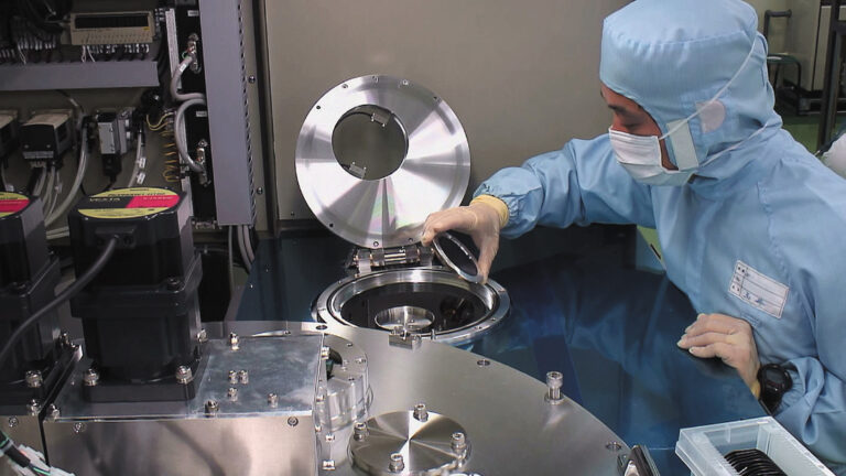
In the stacking process step the freshly cleaved laser bars are picked up from the tape and piled up onto a stack. Needless to say, the laser bars and especially the facets are very sensitive at this stage and the mechanical pick and place process needs to be done with high precision and zero damage. The tape where the bars have been cleaved needs to be expanded. Otherwise it is possible to scratch or chip the facets. Since the laser bars often have an odd form factor (very long and thin), the handling of the laser bars is a task only for the most skilled operators. Ideally, the facets will not scratch on any surface. The laser bar stack itself is structurally somewhat unstable since it has to be open for the treatment both on the front and in the back. It is therefore mostly held in place by applying vertical pressure. The key parameters for this process is to pile up as many bars as possible without damaging any of them and creating a sufficiently stable stack that can be handled into a vacuum chamber for further processing. OptoSystem offers machines that can accomplish exactly this task. The metallic holder in which the bars are held, the jig, has various designs that depend strongly in the bar geometry and in many cases in the traditions at diverse labs or fabs. If you are considering to transfer your manual process into a mechanized process, OptoSystem can give you advice about jigs that will be suited to hold the bars in an automatic stacker. The laser bars are placed automatically from the tape to the stack in a perfect arrangement without touching the facets. After the stack is completed, the jig is closed manually by an operator. This is easy to accomplish due to the mechanical support.
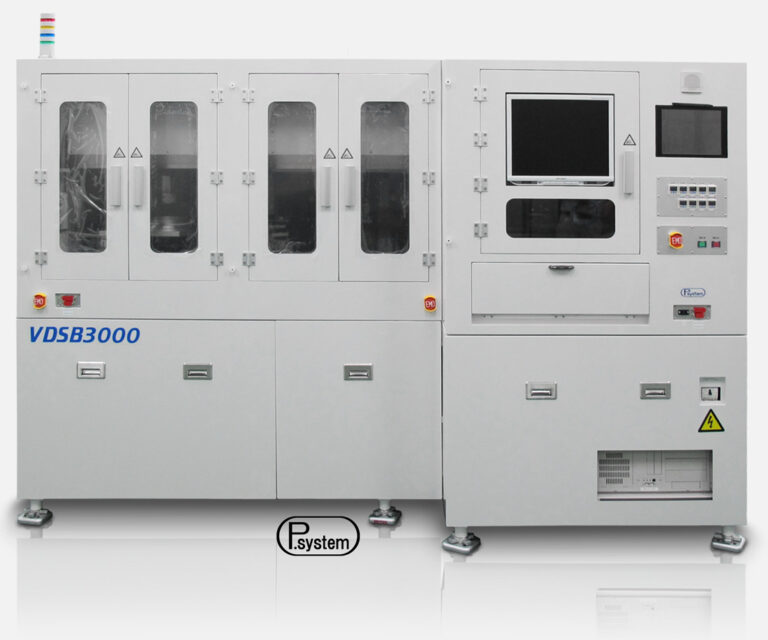
Stacker Unstacker Tool VDSB3000 from OptoSystem. This tool automatically picks up the bars and creates stacks with a defined overcoating. After the coating, it is also able to unstack the bars from the jig back to tape. OptoSystem also offers pure functional stackers because it is technical advised to stack and unstack with different geometry. The positioning is much more precise and it is possible to automatize a larger portion of the process.
Spacer BArs
To stabilize the process, to perform an “overcoat” and to enable automatic unstacking, most manufacturers use sacrifice (spacer) bars of Si or the same material between the actual laser bars. The spacer bars have a triple function. They provide mechanical stability to the stack because they are longer and can be held on the facet planes where normally the mirrors are. This holds the stack in place within the jig. Besides they can be slightly shallower in the resonator length, letting the laser bars slightly protrude into the plasma for a more conformal coating of the laser bar edges (overcoating). It helps separating the bars without damaging the mirror coating by tearing it apart at inconvenient areas that need to remain covered by the mirror. The third reason for spacers is that the automatic unstacker needs them to separate the bars from the stack.
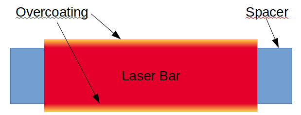
Top view of a laser bar on top of a spacer bar. The spacer bar should be longer than the laser bar to ease handling and bar separation. If the spacer bar is also thinner and the placement is done which high accuracy, the mirror coating slightly fades in into the top and bottom side of the laser bar. This is intended and is called overcoating. The overcoating increases the stability of the mirror on the edge of the bar and since it is an insulator, it prevents current spreading right down to the facet.
Facet Passivation and Mirror Coating
When the facets are cleaved and the periodicity of the crystal lattice is interrupted, the open bonds of the atoms react very quickly with the atmosphere. Especially oxygen leads to a large increase in the nonradiative recombination rate at the surface. In other words, the laser light absorption at the facet can be significant if left untreated. This effect is specially significant for high power GaAs lasers. For InP the recombination velocity at the surface is about two orders of magnitude smaller and and the absorption is lower.
There is a number of various processes that are individual for the different materials and types of edge emitting lasers but all come down to the removal or neutralization of oxygen and the introduction of a component that neutralizes the absorption at the facet.
The neutralization of the oxygen can be done by applying a thin layer or Al that will react with the oxygen to build the insulating and transparent Al2O3. Another method is to mechanically remove the oxygen with ion milling and passivate the facet with nitrogen. The nitride layers seal the surface from further oxidation and form nitride compounds that have higher bandgaps than the bulk crystal and cannot absorb the laser. The most straightforward method is probably to ion-mill the oxygen away and immediately apply the dielectric mirror coating in the same vacuum chamber.
The facet passivation and mirror coating is done in a vacuum chamber with a plasma enhanced thin film deposition system.
Unstacking: Going Back to a Frame in 2D
The bars can be picked up from the stack and placed on trays, tape or other holding containers. It is possible to perform a visual inspection of the top, facets and bottom to sort out bad devices.
Unstacking is not less challenging than the stacking part. Although the positioning usually does not have to be that precise and the facets are already passivated and hence less fragile, it is very difficult to pick up the laser bars without inflicting any damage. After the milling and coating steps the bars often attach to each other while the stack remains to be an intrinsically unstable structure. This makes it difficult to pick up just one bar at a time. Using the spacers OptoSystem’s unstacker tool is able to effectively separate the spacers from the laser bars and pick up the laser bar without damaging it. The unstacker works full automatically and even can be conveniently expanded with the option of optical inspection. The operator just needs to place the jig in the unstacker and remove its top frame.
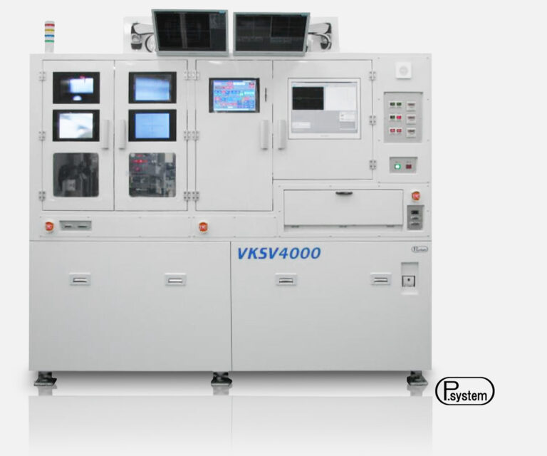
Unstacker VKSV 4000 from OptoSystem combines the task of automatic unstacking with an optical inspection routine of the laser bars on all sides.
Do you like what you see?
We value your feedback, so let us know what you think!
Let us also know which topics you would like to see expanded.
Just give us a call, send us an e-mail or use the form to contact us.