CATEGORIES
Targets
In any sputtering system (the ECR plasma coating tool is one example), the part designated as target is a solid piece of the material that will be sputtered for the thin film coating.
Most common targets are flat in shape and they should be large enough to avoid unintended sputtering of the metallic bearings. Some plasma geometries require cylindrical targets as well. Either way, the target surface is always larger than the actual sputtered area and used-up targets display deeper grooves or areas where the sputtering effect has been predominant. These areas are often denominated as race tracks.
The exchange of the targets is determined by the most used-up area of the target and if the system has a rather homogeneous usage of the target, the exchange cycles can be kept very large. The target production can be expensive and the downtime of the tool during the exchange can be bothersome. Therefore a good usage of the target surface is certainly aimed by the design and geometry of the plasma and involved electric fields. The target often features a metallic holder with water cooling channels to which the actual target material is bonded. The target provider vouches for the high quality of the material, which is free of cracks that would allow the solder to seep to the front and contaminate the coating process.
The exact location, size and shape of a target is strongly tool specific. Some tools have flat targets, which are easier and cheaper to replace. However, some chamber designs demand for targets shaped like a ring, which are much more expensive..
The SputterING Process
To create the vapor-phase species, the ionized gas is accelerated by an electric field to the target, bombarding it. A series of partly inelastic momentum transfer processes between the impinging ions and the target’s material result in the ejection of atoms of the target material (sputtering) from the material lattice into the gaseous state of the coating chamber. In the low pressure chamber, the target particles fly by line of sight or can be ionized and accelerated by electrical forces to the substrate, where they are adsorbed and become part of the growing thin film.
From a practical point of view, electrode-less systems such as ECR plasma coating, in which the energy for the ionization is coupled inductively have the advantage that there is virtually never need to replace the electrodes and therefore they offer long time operation without maintenance breaks. Radio frequency RF systems operating at 13,5MHz and microwave MW systems operating at 2,5GHz are among the most popular ones. A further advantage of an oscillating electric field to maintain the plasma is that a DC field only works with conducting target materials. AC fields do work with both conducting and insulating target materials. When the target has an insulating material and a DC field is used, its overcharging leads to undesired arcing.
In the ECR plasma deposition system, an additional RF field accelerates the ions towards the metallic target. The impact of the ions on the target dislocates target particles that are eventually ejected (sputtering) into the coating chamber and become part of the ionized plasma. Both the microwave and the radio-frequency electric fields contribute to the plasma on their own. The sputter energy can be separately controlled from the electron energy. The plasma generates charged particles that are used to bombard a target (sputter effect) and to transfer energy to the growing film.
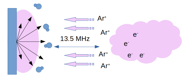
An additional RF electric field is applied between the target material and the plasma. The Ar+ ions are strongly accelerated towards the target. Due to the collision, particles of the target are sputtered into the chamber gas.
Why is the ECR Plasma Coating so special?
A very distinctive characteristic that enables the ECR plasma system to provide films with outstanding optical characteristics, is the separation of the plasma generation from the sputtering species generation. In many sputtering systems, the plasma generation and the target are part of the same electromagnetic set up: The target is an electrode of the plasma generating field. In the specific geometry of the ECR plasma coating tool the plasma is generated by an inductively coupled microwave field, while the electric field leading to the sputtering is an independent RF field. The strong microwave field coupled with the resonant magnetic field creates a high local density of ionized gas. The sputtering field does not have to be that strong to create a large enough sputtering rate. Hence, the sputtered particles can be produced in sufficient quantity while their energy is in the range of just 10-30 eV. This is very difficult to achieve with other set-ups and will have a significant influence in the thin film growth and the achieved physical properties.
The way that the ionization is achieved is responsible for certain film properties. ECR plasma coating is able to generate a sufficient growth rate with relatively low energies. The sputtered species reach the substrate with kinetic energies in the range of few 10eV and therefore do not damage the underlying layers of the substrate. The generation of hot electrons in the ECR plasma coating system can be controlled separately and these provide energy to the growing film, which is crucial to achieve a bulk-like structure. Thin films grown with ECR plasma technology have demonstrated outstanding purity and transparency, crystalline structure, as well as unparalleled resistance to corrosive environment.
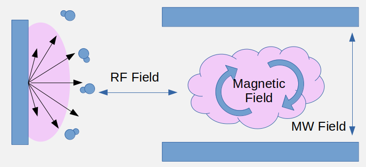
The combination of the strong microwave (MW field) and the synchronized magnetic field brings about the electron cyclotron resonance ECR plasma. The RF field to generate the sputter species can be adjusted independently.
Do you like what you see?
We value your feedback, so let us know what you think!
Let us also know which topics you would like to see expanded.
Just give us a call, send us an e-mail or use the form to contact us.