CATEGORIES
The Meaning of Facet quality
good mirrors with low absorbtion
A good facet quality is paramount to a good laser since the laser light needs to be bouncing back and forth between the facets. The laser light can become very intense and even minor absorption in the facet will literally melt a hole in it. The facets must be parallel so that the photon path does not diverge off the gain medium when reflected. Also, the facets must be perfectly plan and smooth. The power reflectivity of the facets exponentially decreases with roughness. The main problem with rough facets would be photons being scattered back at different phases and angles and hence contributing to destructive interference and canceling out the coherence of the laser light. As a result such a laser would have a very poor total gain.
An additional problem with rough facets is the increase in surface through the roughness that maximizes the amount of dangling bonds that can generate nonradiative recombination centers. These will absorb the light and heat up, promoting a facet meltdown called catastrophic optical damage.
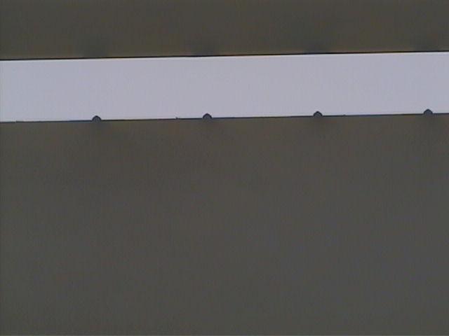
A good example of a perfect facet on a GaAs substrate obtained with scribe and break tools from OPTOSYSTEM. Since the laser quantum wells have been grown on a GaAs crystal, when properly cleaving the crystal, its absolute mirror quality comes out.
Raw Facets and C.O.D.
There is no better facet than the crystal plane itself. Therefore the applied technique is to create a crack or a weak link with a diamond or laser scribe close to the laser facet and then apply force to allow the semiconductor to cleave along its own crystal plane more or less by itself. If well performed, the result is a perfectly flat and straight facet of the crystal itself that builds a natural dielectric mirror between the semiconductor and the air and is parallel to the opposite facet. In a primitive version of an edge-emitting laser diode, the cleaved facets act as mirrors due to the strong refractive index (n) difference between the semiconductor (n_s) and the air (n=1). Due to this effect described by Fresnel equations, the typically used compound semiconductors come with built-in mirrors that reflect ~30% (~20% for GaN and 40% for InSb) of the laser light at the cleaved facets back into the semiconductor. This is sufficient to achieve lasing in these structures. Yet, although the gain region renders itself transparent to the laser light by the inversion of states, the facets themselves will likely absorb a part of the laser light. At higher laser powers, untreated facets will be the first to heat up. In the area where the laser light is absorbed, the heat will easily elevate the temperature to the point of melting the semiconductor crystal irreversibly destroying the laser. This failure mode is pretty common and is named Catastrophic Optical Damage (COD).
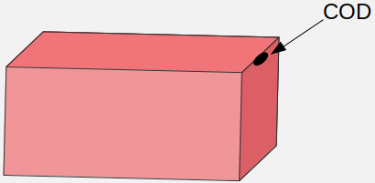
Where the laser light hits the facet, very high light intensities can be easily achieved. Although the semiconductor itself is transparent to the laser light, the facets are not and absorbtion of laser light leads to a quick heat-up that will melt the semiconductor. This sudden form of laser death can be observed on the microscope as a dark spot on the facet. In all cases this form of failure is irreversible and in most cases it ends the lasing capability of the device for good.
Improving the Facets pays off
Facets of commercial devices are coated with dielectric layers of alternating refractive indexes (Bragg mirror) to increase or reduce their reflectivity at specific wavelengths. One of the facet mirrors is tailored to perfectly reflect the laser light and the other facet mirror is engineered to have a specific reflection trading off the threshold current versus the slope efficiency. Otherwise the laser light would exit the semiconductor from both sides alike. Non-radiative absorption mechanims are mitigated also by adjusting the refractive index of the facet coatings to the semiconductor itself. This does increase the COD threshold and lasers with very high power densities become feasible. The light exiting the laser from its non-reflective facet is usually coupled into an optical fiber, while the rear high-reflecting facet often is non totally perfect and does leak a small amount of laser light. This can be collected by an attached monitor photodiode to enable active control of the output laser power.
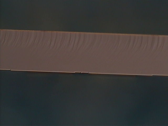
In this example a facet of a InP substrate obtained with scribe and break tools from OPTOSYSTEM. The striations are a normal feature in InP and do not affect the active emitter, which is on the bottom edge.
Do you like what you see?
We value your feedback, so let us know what you think!
Let us also know which topics you would like to see expanded.
Just give us a call, send us an e-mail or use the form to contact us.