CATEGORIES
Cleaving Tools
Finally when it breaks
Up to this point we have discussed at length the most important aspects of crystal planes and scribing. For the actual propagation of the fracture a bit of force must be applied. Good results require certain conditions on the crystal and the scribes, but a good cleaving technique is absolutely necessary as well.
Once the scribe has set a physically localized material weakness, applying pressure will cause the crystal to cleave and thus separate the wafer or a portion of it into the individual laser bars (and later if desired the laser bars into individual chips as well). Applying a bit of pressure, such as bending the semiconductor over an edge, will lead the crystal to break; however, to ensure that the crystal will cleave along the plane free of terraces, the cutting edge must be perfectly aligned with it. Tools from Opto System use machine vision in combination with precise alignment to ensure that the cutting edge is exactly aligned with the scribe and the crystal plane. In the Breaker tool the semiconductor is pinched between a cutter from the backside and two supports on the scribe side, allowing the crystal to slightly bend between the supports. This delivers enough pressure to fracture without damaging the structure. If this is not enough to reliably break, the process is repeated with additional cutter depth until the break occurs. At the same time it is necessary to prevent the cut facets from rubbing on each other, since this can lead to chipping. Striations can be a problem too when the break springs between parallel crystal facets until it stabilizes.
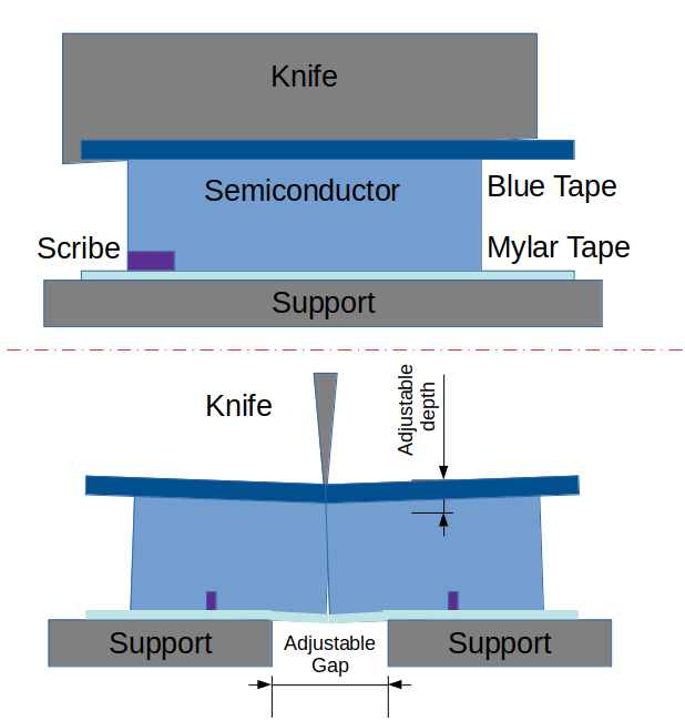
Some Cleaver and Breaker from OPTO SYSTEM have a three-point breaking mechanism using a knife (top) and the gap in a support (bottom).
Breakers and Cleavers from Opto System
The breakers from Opto System have a dedicated design and geometry that was originally developed for the mass manufacturing of CD and DVD laser diodes (and LEDs). The optimized operation of these tools have a proven track record of high facet quality on a huge quantity of laser bars under the most difficult conditions while maintaining low cost of ownership, high production yields and high manufacturing throughput.
In this conception, both the scribing and the breaking is done in separate machines. This makes it possible to optimize each processing step individually with a large number of parameters. There is no necessity to make any compromises on the process quality and speed to be able to combine the scribing and breaking function into one machine. Having two machines also gives you the ability to process two wafers at the same time. The scriber is optimized for your material that may be scribed with a laser or with a diamond.
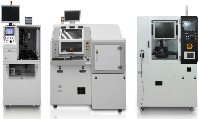
Opto System manufactures three different breaker designs that have their own specialties. The wafer breaker WBS4000, the breaker LDH-100TSX (or LDH-50TS) and the tape cleaver LDTH-100TS. Each machine is designed with unique features to their own specialties.
Primary Cut for Laser Diodes
Primary Cut: This so-called primary cut at Opto System deserves special care to avoid any “terraces”, chipping or any other facet damages. Secondary Cut: The cut separating the chips laterally -the facets that will not be reflecting or passing laser light- are called secondary; less precautions are necessary because they do not need to have optical interface quality.
Avoiding defects is still crucial, thus the bending force must be perfectly aligned with the desired plane. To achieve the best results, bending radius, speed of the cut, knife orientation, impacting angle and other parameters must be adjusted to the specific material properties and geometry. In many cases, the stress on the wafer caused by mismatching epitaxy will also influence the results.
The scribes for the primary cut are never set directly over the optically active areas, but before (or after) them. The crystalline property of the wafer and some bending force will propagate the scribe and split the semiconductor in two.
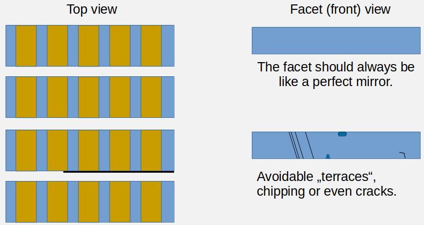
An example of an avoidable problem that reduces yield on laser diodes.
The knife and anvil Method
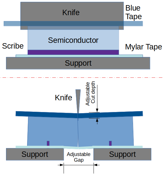
The Laser Diode Cleavers LDH-100TSX and LDH-50TS are our most popular breakers to generate mirror-like facets for edge-emitting lasers. Both machines work by the same principle. The main difference is the area that can be processed: The LDH-50TS can work with an area of 2” while the LDH-100 TSX can process a full 4” wafer. Since wafers are often split by hand before the actual fine processing, 2″ is not a small number at all.
The wafer lies face down protected by a thin Mylar layer. The scribes are now on the bottom side. From the backside (on the top) the sharp knife presses down exactly on the opposite side of the scribe. The wafer lays on an open support that acts as an anvil. The opening of the support is adjustable and allows to define the bending radius of the wafer. This provides constant optimum conditions for breaking which can be adjusted to different thicknesses and situations, delivering reproducible results.
The Tape Method
The knife and anvil method is fast and reliable but since the semiconductor cannot bend freely too much, a lot of the cleaving is done by the impact force of the knife.
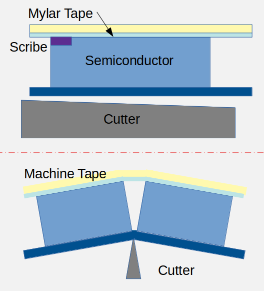
Opto System has developed the tape cleaver specifically to increase the production yield for laser bar cleaving. In this tool, the supports are substituted by a tense tape. The semiconductor is then hit on the back side and it is allowed to bend way more than in the case of the anvil breaker due to the flexibility of the tape.
The tape cleaver is unique in its kind and it has been specifically developed to improve the primary cleave for high power edge emitting laser diodes on soft materials with cubic crystal structure such as GaAs. Especially for high power laser diodes with very high quality requirements of the facet and when the resonator cavities are not too short.
The wafer has much more freedom to bend in a large radius. In the tape cleaver both the speed of the cutter as well as the total hub can vary much more than in the case of the anvil cleaver. The large bending radius helps prevent chipping since the cleaving stress distributes throughout a larger area and it is less focused on a single spot. When the appropriate threshold to propagate the scribe is reached, the bar snaps open.
The tape naturally stretches when the blade hits, pulling the semiconductor laterally apart. This facilitates the cleave and prevents the fresh facets rubbing on each other.
The bending force can be distributed differently due to the flexibility of the holding tape and the larger bending hub. In this process, the different distribution of force over the semiconductor allows the cleave to propagate creating a very reliable and mirror-like cut. Since the tape expands and stretches, less chipping and damage of the facets is the result.
knife and anvil for thicker substrates
The wafer breaker WBS4000 is specialized on very tough-to-break wafers that are thick and/or very hard. Its original purpose was to break LED wafers of SiC and Sapphire. Nowadays, they are used in combination with laser dicing and scribing devices, to ensure that the devices do separate in 100% of the cases. The laser light penetrates into the wafer and locally melts the semiconductor, creating a stress, that creates a sufficient mechanical stress to separate the devices. In many cases, after the laser dicing, the wafers are expanded on tape and the devices break apart, but unfortunately, some devices stick together. The wafer breaker provides an additional mechanical stress that ensures in a quick process, that the separation is completed. This additional process also enables the process engineer to reduce the laser power and avoid wafer damage.
The wafer breaker features a very large knife that hits the wafer once at its whole length with the strength of up to 100kg. The touch sensor enables the process engineer to precisely define, how deep the knife goes into the wafer and hence how strong the deformation of the wafer will be. This deformation is also determined by the size of the opening gap at the front-side support or anvil, which is automatically adjustable for each breaking event.
Depending on the dimensions (thickness and the lateral size) of the piece to be broken, different settings for the support gap and the depth of the knife can be selected, to keep the breaking deforming bending stress optimized for the piece you intend to break. It will depend on the thickness and the lateral size.
The vision system ensures that the scribe, the knife and the support gap are perfectly aligned and centered, distributing the forces evenly. The wafer lies face down protected by a thin Mylar layer. The scribes are now on the bottom side. From the backside (on the top) the sharp knife presses down exactly on the opposite side of the scribe. The adjustable open support acts as an anvil to allow and determine the bending radius of the wafer. This provides constant optimum conditions for breaking which can be adjusted to different thicknesses and situations, delivering reproducible results.
Do you like what you see?
We value your feedback, so let us know what you think!
Let us also know which topics you would like to see expanded.
Just give us a call, send us an e-mail or use the form to contact us.