CATEGORIES
Vacuum Chamber
The deposition takes place at very low pressures. Low background pressure allows the sputtered species to travel unobstructed from the target to the substrate without colliding with gas molecules. It also makes it less likely, that gas atoms are incorporated into the growing film.
Some physical characteristics of the growing film are influenced by the background pressure such as the film stress, the growth rate and sometimes the thickness homogeneity of the deposited film.
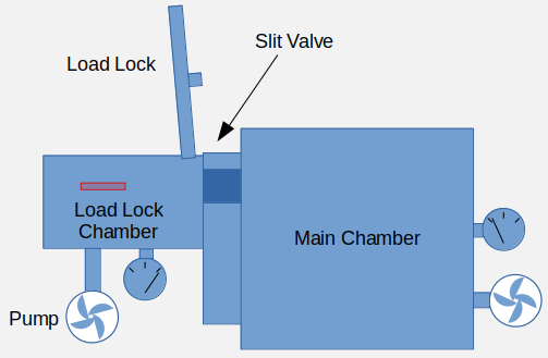
The required background pressure is achieved through turbomolecular pumping. To avoid long evacuation times, the coating chamber is always kept under vacuum, while a load-lock system is used to exchange the substrates. The load-lock chamber is connected to the coating chamber through a large airtight valve that only opens to transfer probes. The load-lock chamber can be pressurized and evacuated quickly while allowing the deposition chamber to remain under vacuum. A robot arm is used to transfer the substrate between the deposition chamber and the load-lock after the latter has been evacuated. If there are several deposition chambers, the robot arm can be used to transfer the substrates between the deposition chambers as well. The load-lock system enables a high throughput with very low idle times.
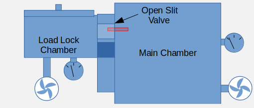
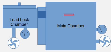
The pic on the right shows how a load lock works schematically. The sample can be loaded (top drawing) by flooding the load lock chamber with air and opening the loading door. In the second stage (middle drawing) the load lock door has been closed and the pump has evacuated the load lock chamber to a large extent. The slit valve opens, connecting both chambers, and a robot arm within the tool picks up the sample from the load lock chamber through the open slit valve to the main chamber. In the last stage (bottom drawing) the slit valve closes. The load lock chamber can be loaded with the next sample. The main chamber is under vacuum during the whole process.
Gas Lines And Pumps
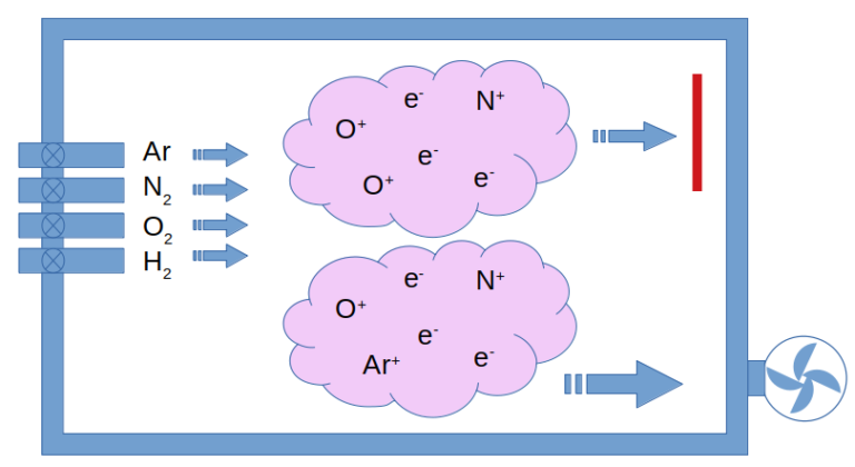
The plasma gas is provided by an elaborate system of gas lines and mass flow controllers (MFC). These precisely dose a small flow of gas that is needed to generate the plasma. A background pressure of around 1×10⁻³mbar of non-reactive noble gases is a normal value. Argon, being the most common noble gas in the Earth’s atmosphere, is a logical choice. The plasma of argon is pink to blue. One of the strengths and complexities mastered by ECR is the coating of insulators. In this case, reactive sputtering is often done by adding a chemically active gas to the plasma. In reactive sputtering the metallic component of the insulator such as Al, Si, Ta… is provided by bombarding the target with the plasma while the oxide or nitride are provided by adding O2 or N2 to the plasma gas. The film growing on the substrate is then a stoichiometric combination of both components forming the insulator such as Al2O3, AlN, SiO2, Si3N4 and so on.
One of the most complex and difficult aspects of any plasma-enhanced deposition is the gas mechanics, since the pumps are working at full speed while the different noble and reactive gases are flowing into the chamber to be partly ionized. Mastering the gas flow in the chamber is necessary because it influences the physical properties of the growing film. The ECR plasma coating system even enables one as well to grow for instance SiOxNy films at very precise x and y numbers. With this trick, it is possible to engineer the diffraction index to a wide range of values while keeping the absorption value constant near zero.
Gaseous hydrogen is also added for the growth of amorphous silicon thin films and amorphous diamond (C) films.
The added gas for the plasma is substracted from the chamber primarily by the turbomolecular pump but also through chemical reactions and incorporation in the coating film.
ECR Plasma Source
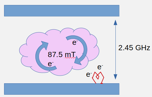
In the ECR plasma coating system, the plasma is generated by a high concentration of energized electrons in a small doughnut-shaped volume:
A hot filament primes the chamber with free electrons. The MFCs provide a gas flow that sets the background pressure at around 10-3 mbar of Ar. The electrons are accelerated by an alternating microwave electric field with 2.45 GHz and kept in a toroidal volume by a matched alternating magnetic field of just 87.5mT. Since the electrons are contained in a small volume, it is possible to generate a large number of collisions within that contained region and sustain the plasma with the electrons that are constantly generated by the collisions at an extremely low gas pressure. The collisions ionize the gas and electrons are constantly generated. Upon ionization, the species are susceptible to the electromagnetic fields applied by the generators and can gain a significant amount of kinetic energy before they hit another particle.
The applied magnetic field strongly influences the electrons with their low masses. Even small fields force them into a spiral movement that translates into a much longer path within the plasma and therefore increases the chances of collision with a gas particle. These so-called magnetron systems can sustain a plasma with lower background pressure and smaller power without the ions neutralizing quicker than they are re-ionized by an impacting electron. If the magnetic field is carefully adjusted to accelerate the electrons into a circular path that resonates with the applied AC electric field, an even stronger collimating of free accelerated electrons in the plasma region is possible. In this case we are talking of an Electron Cyclotron Resonance (ECR) plasma.
Do you like what you see?
We value your feedback, so let us know what you think!
Let us also know which topics you would like to see expanded.
Just give us a call, send us an e-mail or use the form to contact us.