CATEGORIES
Diamond Scribing on GaAs and InP
Crack through pressure
The sharp edge of a cut diamond is dragged along the cleaving street. The action of the scribe plastically deforms the surface of the wafer and creates cracks beneath the surface. Some of the cracks will be the desired cause for fracturing. After the scribe, a small incision is visible on the semiconductor; its depth is not the main reason for the cleaving results but the depth of the inflicted crack.
The depth of the scribe groove that is visible from the outside on the semiconductor surface does not have the main effect on the cleaving but the crack it produces. The most important crack for cleaving is the median crack perpendicular to the surface. It’s depth is paramount on the subsequent fracturing of the semiconductor.
The sharp edge of a cut diamond is pressed against the semiconductor crystal. The localized pressure causes it to crack.
Applying The Right force
The median crack depth is proportional to the applied diamond force. The largest scribe force also produces the largest amount of damage to the surface, generating chipping and loose particles. Other cracks that the scribe produce are lateral cracks beneath the surface and radial or chevron cracks on the surface. The lateral cracks can pose a problem if they propagate to the laser structure and cause operation failure. The chevron cracks may cause difficulty by guiding the median cracks out of the scribing direction and into another neighboring cleavage plane. This is often the case with hexagonal lattices such as wurtzite GaN. It is important to eliminate chevron cracks and minimize lateral cracks while producing deep median cracks. If the scribe or break is too strong, chipping, particles and unwanted cracks will damage the devices. The applied scribe pressure is a very important parameter to control the results. To this purpose, the original system from OptoSystem with digital pressure control really helps to realize the stable diamond pressure along the scribe and from scribe to scribe, wafer to wafer.
Diamond scribers from OPTOSYSTEM have a tried and proven method to make sure that the diamond pressure stays constant during the entire procedure.
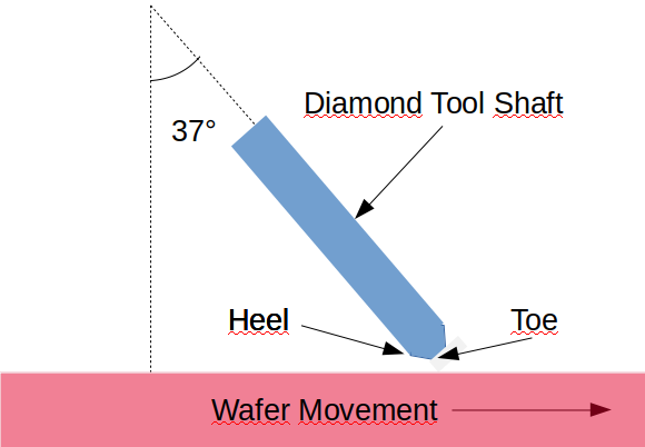
Scribing Angle: Geometry of the Diamond Cut
Another critical way to significantly influence the median crack depth and behavior is by applying a more or less aggressive scribe angle. There are different types of diamonds depending on along which planes the raw diamond has been cut. Among others there are 3P, 4P, 5P and 8P, accordingly to the amount of points on the crystal available for semiconductor scribing. The crystallographic orientation of the diamond tools exerts a great influence on the cutting deformation. Depending on the semiconductor material, the epitaxy and metallic connections on top of it, different diamond types can be used. The diamond may offer different edges to work with.
For some diamond configurations there are different application angles that are designated as “heel” or “toe”. When the cutting is done with a salient angle of the diamond, the scribing pressure is smaller as when the angle is more inclined. The diamond angle has therefore a very important influence in the results and needs to be carefully adjusted for repeatability. Variation in the diamond scribe tip and uncertainty in determining the exact angle of the diamond scribe tip results in a significant error and variation in the fracture results.
The diamond angle with an OptoSystem tool can be adjusted very easily with the tool computer and an integrated motor. OptoSystem’s engineers will show you how to adjust the diamond angle for optimum results.
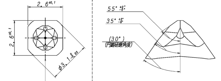
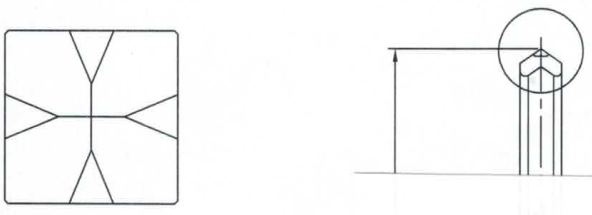
Diamond cut with eight points (top) and four points (bottom). A diamond cut with four points is a very popular choice. There are other cuts with slightly different properties, such as the three point and the five point cut. All of them are supported by OPTOSYSTEM.
Diamonds are not forever
The wear of the diamond will gradually reduce the sharpness of the diamond edge until the scribing effect will subdue. There appears to be a slight reduction in the median crack depth with increasing wear. Fortunately this effect tends not to be too large during the normal wear of the diamond but is is mandatory to change the diamond edge after a certain amount of scribed meters since the scribing just stops working after a while. Preventive regular maintenance is advised turning the diamond tool to an unused diamond edge or to an altogether new tip. The diamond scribing tools from OptoSystem record the accumulated scribe length in their computer and provide alerts, asking to change the diamond.
For cleaving the mirror facets, only a short scribe is made, so that the cleaving can propagate on its own, producing a mirror-like facet. In the case of breaking chips apart, the break plane is parallel to the laser emission plane. The separation of the chips does not affect mirror facets at all and hence their smoothness are not really relevant. In this particular case, the scribe is usually continuous along the breaking street. This increases the breaking yield without holding any disadvantage.
It is also possible to apply a ‘dashed-line’ type of scribe; for instance, when a material that is hard to cleave needs more “guidance” while the portion of the cleave corresponding to the laser emitting area is left to cleave naturally. There is always a certain number of options that will achieve different results. OptoSystem engineers will help you with their extensive experience on different material systems. The diamond scriber from OptoSystem works with an integrated intelligent pattern recognition system and can set the scribes fully automatically and with the optimized settings for the specific wafer.

Why an Automatic Diamond Scriber?
Diamond scribing was very common in the semiconductor industry 50 years ago before it was replaced by saws. Nowadays, diamond scribing is mostly used for III/V zincblende compound materials in the {110} set of planes such as GaAs and InP and in the glas industry. There are some reports of diamond scribing for GaN, sapphire and silicon-based MEMS but they are rather rare. Diamond scribing is a process that does require some level of mastery but once acquired, perfect mirror facets are relatively easy to achieve. Besides, this method virtually produces zero kerf loss hence allowing die density to be maximized, no abrasive particles, no post-process cleaning is needed and most importantly, no residual stress is created.
OptoSystem tools use a state-of-the-art visual recognition system to search for the structures on the wafer to be cut. The automatic scriber will rotate the wafer to align it to the structures and wafer flat and will place the scribes fully automatically at the designated scribe angle, speed, load and length. The machine is able to precisely adjust the touch-down position and exact pressure from the first to the last scribe. This is ensured with an original technology that sustains the pressure of the diamond tip along the scribe. Although it is not impossible to place some scribes with simpler tools, you will be amazed at the speed and reproducibility of an automatic tool from OptoSystem. Besides, you will benefit from the scribe and break expertise that OptoSystem has built up with multiple customers and materials in the last decades. Please contact us today and provide some samples for testing. OptoSystem will help you to achieve perfect results using a diamond scriber with the settings that work best for your specific process.

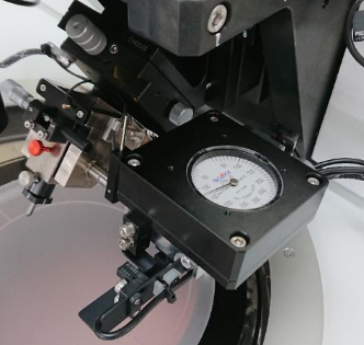
Diamond scriber OSM-100TS from OptoSystem. A market leader from Japan for scribe & break equipment.
Do you like what you see?
We value your feedback, so let us know what you think!
Let us also know which topics you would like to see expanded.
Just give us a call, send us an e-mail or use the form to contact us.